REPLICATIONS LOG BOOK from: http://www.overunity.com/index.php?topic=7679.0 I would like to congratulate all the fellow experimenters which have been able to replicate successfully my Kapagen generator...
Jean-Louis Naudin - JLN Labs
Latest published replication: July 2nd, 2010 |
# 1 - June 9, 2010 - Kapagen replication by dragon
I've made several attempts with different coils and this is one of the better ones. The whole thing is Tesla basics as you can see in the diagram of the circuit. The picture's show it running a small 40 watt bulb at around 7 watts of input, the variac is set at around 50 volts. The NST is a 120V input with a 6500 volt .02 amp output. I have 2 earth grounds on this one but the second doesn't seem to add anything and can be removed without changing the light intensity or input requirement. One is required.
I've found by playing with various coils and bulbs it's not so much the wattage of the bulb in as much as the resistance of the bulb or bulbs. I have no real way of measuring the output at a wattage level, no claims are being made.... just an interesting experiment.
.....
Since I really don't know how JLN or Kapanadze is actually going about it I've been theroizing on my own of how to accomplish it and came to the conclusion it's nothing more than a reverse tesla coil. Instead of putting HV low amps into L1 and converting it to extreemly high voltage you do just the oposite... put the HV into L2 and convert it to lower voltage and higher amps through L1. The trick is getting L1 to resonate with L2 in its reverse form.
L1 being very low inductance using the earth ground through a load creates a psudo tank in which L1 can reach high amps. I still don't have the resonance dialed in quite right with this one although it seems to drive L1 reasonably well ( L1 being the 6 turn coil - L2 being the 90 turn coil - L3 the reversed 30 turn ). L3 is used to raise or lower inductance to help match the two. It might even help to make this one adjustable to some degree.
Getting bulbs to light is a matter of shuffling through various resistances to achieve the correct response. I've run 175 watt mercury bulbs with it but those react like FL's and in my mind doesn't really constitute wattage in as much as a voltage response.
I've been doing some tests with a 150 watt halogen and it lights nicely produces lots of heat but is far from full bright. At 150 watt input it will be blindingly bright (sun like to your eyes), driving it with this set up it's bright but not blinding and is using about 35 watts to get it there although I can get an orange glow with lots of heat at 10 watts.
I need to do more work with this coil to dial in the resonance a bit better....
Fun stuff....

 |
# 2 - June 9, 2010 - Kapagen successful replication v1.0 by romerouk
I am using 260w in the system and output is at least 500w.The bulbs are more than fully powered. After few more attempts I have destroyed 2 of them. I will have to get some more bulbs tommorow and see how many I can connect and still keep full brightness.I tryed to measure voltage across one bulb and it shows 335v-ac but all my meters are digital and I am sure it is not right.I need to get some analogic multimeters to find the amps and volts at the output.Few minutes ago I have started the system using DC to power the system an now I can see that DC is the only way to keep the system running for longer period of time.Using ac the spark gap becomes very hot as with dc it is much better.Also having a capacitor 90.02mf) connected in parallel with the load, keeps the flickering under control. I hope the picture attached will make all understand the basic of it.
 |
# 3 - June 10, 2010 - Kapagen replication v1.1 and 1.2 by romerouk
I have posted another 2 video-clips testing circuit with high voltage AC then using DC as power source.
...
I am in UK, using 240vac. Every bulb is 100w and I have connected 9x100w. Sorry I forgot to show that in the video... I will do it next time.
I get around 1.6amp using AC to power the system but when I use DC it drops to around 1.15.
...
tube = 5.5cm/140cm - wire 4mm stranded except the big coil = 10mm stranded MOT I have no information about it. the tube is PVC 5mm thick
I have no connection with J L Naudin.He lives in France, I live in London - UK, foreigner not British. I have a lot of respect for all his work. Everything he does is always well documented, tidy, showing a lot of knowledge in his work. I am very small comparing to him, many of us here are.I think that he is not trying to prove overunity with kapanadze replication, it is just showing proof of concept.Many applications. on J L Naudin website are proof of concept but enough to give us a start in many directions. For J L Naudin free energy is a fact not just supposition. I am sure he has many devices built showing extra energy. One thing I found is that you need both earth connections directly to the ground and about 10m distance. I didn't try longer distance as I don't have more lenght in the garden.In my first attempt I had one earth was comming from the water supply and the other one from a copper pipe I fixed in the ground.That showed me 2.3 amps for 500w load, then I have fixed another copper pipe in the ground at 10 m distance and I got about 1.6a for 900w load.MOT stays just a little bit warm in my case, maybe you have a defective MOT,run it without anything connected to see if it still gets hot, check capacitor value, if it is too high might create the problems you have.Not recommended to start the device inside the house as it will interfere with all electrical equipment, it does in my case, I have almost destroyed the tv, running the device in the garden.It is a lot of radio waves generated by the device and this is another problem at the moment.Turn off all electrical appliances in the house while testing. Kapanadze replication v1.1 used 1.7A X 240ac = 408 watts input
Kapanadze replication v1.2 used 1.16A X 240ac = 281 watts input
Success all! |
# 4 - June 11, 2010 - Kapagen replication by callanan 

|
# 5 - June 11, 2010 - Kapagen replication by retrod
Here is my first attempt, so don't laugh . I used a large variac on the 120vac input to the MOT (not shown). I had to work in the basement indoors so I used a copper water pipe feed for one ground and an iron floor drain pipe that leads outside & underground for the second. The spark gap is a non resistor sparkplug with a vice grip for a heat sink. The lamp is a 200watt 120 volt. I used the DC circuit with a small HV cap.
First results:
MOT gets very warm and the 20amp mains circuit breaker trips after 15 seconds of operation. Spark gap is electric blue, not violet. Please be careful with this circuit the voltages present are indeed dangerous.
Dave |
# 6 - June 12, 2010 - Kapagen replication by retrod
Second attempt. After this mornings smoke test I almost gave up. Then there were some encouraging posts and advice. Here is some progress to report. I noticed on my set-up it works much better with high resistance loads. I started with two 40w light bulbs in series and then thought to try fluro tubes. I am up to six tubes in series with the two original 40w lamps. All the fluro tubes were removed from service a year or more ago as dim or non lighting. It reminds me of when many of us were adding LED's in series working with Dr. Stifflers SEC, what fun!
I have no way right now to measure input current. The voltage out of the variac is 90 volts. The spark has become very quiet with this load. I may post a short video on youtube later. |
# 7 - June 15, 2010 - Kapagen replication by woopy Hello romero and all
OK i am almost ready for a first test. I did the coil exactly as Romero that is 84 turns plus 22 turns plus 6 big turns.the coil 1 and 2 have the same stranded wire (blue) and for the big coil (green and yellow) there is 7 strand of plain copper, the center is made with 4 stranded copper and something torsaded for connection to one ground line, plus the main blue wire connection to the spark gap. the mot is rated 700 watts. I will use it directly (without the cap and diode for a first test. What do you think ? Or can i use the MO cap (0.95 micro farad and 2100 volts) and HV diode.?
I will ground it with 2 ground line conducting to 2 galvanised steel bar going 1 meter deep in the ground. and separated about 15 meter. I intend to use a wire with 3 time 1.5 mm2 bounded ,for the ground lines . I intend to begin with a halogen 500 watts what do you think ?
If it works, i will post the pictures of the construction of the coil step by step.
good luck at all
Laurent |
# 8 - June 16, 2010 - Kapagen replication by retrod Some numbers & a video.
MOT is a OBJY2
Input Voltage : 120vac
Input current : Measured at output of variac 4.0 amps avg
Load: Six 200w 120v Lamps
Earth Grounds : First: 200ft iron pipe (water well). Second: 10 ft driven rod, copper clad
Spark Gap : Champion J-14 with neo magnet attached
Air temperature was 68 degrees Fahrenheit
MOT Temp at start 84 F
MOT Temp at end 107 F
Run time approx 4.5 minutes |
# 9 - June 16, 2010 - Kapagen replication by woopy Hi all
the rain stopped shortly , and could not prevent me to have a second test.
Took all precaution as per Stefan and 3,2,1 go
yaouuh it works very fine. The bank directly connected to the grid does simply no light at all, but with the Kapagen it is near full brightness. i have AC current , no cap at all. I did not make any measure but the grid fuse did not even break. another thing i have a radio on at 10 meters from the kapagen and nothing , no grrrrrbbrrkkkkkk, at all in the radio.
OK and the rain comes again
hope that tomorrow it will be better weather to make some measurements.
just for info the bank as a resistance of 400 ohm. when i connect the bank to the grid, my clampmeter shows 130 ma at 230 volts AC just another thing the bank was on and stopped only when i switched off. but when i tried to take the measre of resistance it was impossible. Than i checked the bulb and one was broken. I mean it seems that i probably had the arc in the bulb which make the bulb on even if the tungsten filament is broken. What do you think?
good luck at all
Laurent   |
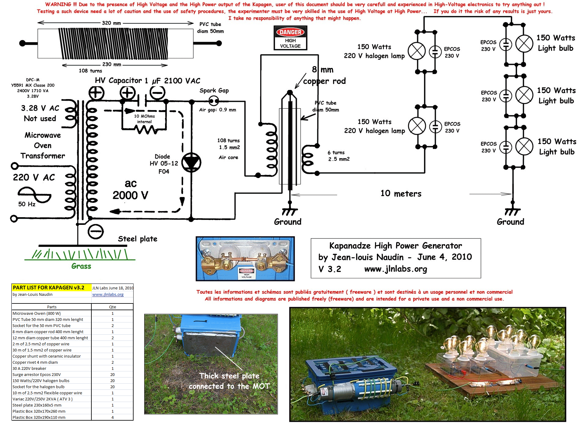
June 18, 2010 - Working KAPAGEN diagram now released by JLN... 
Click on the picture to enlarge |
# 10 - June 21, 2010 - Kapagen successful replication by Robert Dear Mr. Naudin,
Good news!
I got 1800W out and the MOT stays cold even the inlet power meter indicates 800W. I think that’s a real sign of OU. I have 2x150W halogen + 18x 100W bulbs (fully bright) and all serial. If I would have more lamps I think they would shine fully too.
I observed that with the 1N5408 diode didn’t work – but with the BY255 it works very well – just they get hot, so I add cooler.
I don’t know way you changed the coil setup but with the coil relation 22 – 84 – 6 its working quite well.
Many thanks and br.
Robert |
# 11 - June 23, 2010 - Kapagen successful replication by JujuHi Guys!
I made a video of my setup, is my first one!
i putted some lamps of 60w others of 100w, all in series with a fan/ventilator of 100W... i putted the fan in the end of the sequence going to ground, because it haves a capacitor of 230V, i was affraid it can blow up if it takes all the primary voltage! 2 lamps in the video are not lighting well, but i think it was some problem with them!
this thing can feed all type of devices, not only lamps!
and it is not so spooky as at seems, when the adrenaline goes up, the fear fades! spectacular!
my output dont work well with dc, as you can see, dont used any caps!
dont took measurements because my DMM cannot read alternate current, only dc... This vid is dedicated to the portuguese team in the worldcup, that win today 7-0 against North Korea
Enjoy!
All my thanks specially to JLNaudin, romerouk, laurent, xenomorph, jonny and the rest of the FE crew!
|
# 12 - June 25, 2010 - Kapagen successful replication by TomB-455 Dear Mr Naudin,
I have tried to replicate your coil and it works!
most of the setup is the same as yours, m.o.t. 800 watt, in dc mode. 10x150 wats halo-bulbs fully bright!!
i checkt my variac (but didn't put it on camera) and it was at 165 volts!!!
exept for the 23ccw turns on the entrance of the coil, those whre nessecery to reduce the input current.
the pictures are folowing soon. i did make a video though.. ;)
best regards,
TomB-455
This is an replication of J.L.Naudin's 'kapagen'.
I used for this setup; (V2)
M.O.T. 800 watt (D.C. setup),
10x150W halogen lamps(1500watt total) in series.
Variac 1,5kva.
Coil setup= prim.-88t(cw)+ 23t (ccw) , sec 7t(ccw).
The lamps are burning at 165 volts by 1.28 amps input on the 'kapagen' , these figures fluctuating in diffrence of +/- 5%
|
# 13 - June 28, 2010 - Kapagen successful replication by magnetflipper |
# 14 - July 1st, 2010 - Kapagen successful replication by txqnl |
# 15 - July 2nd, 2010 - Kapagen successful replication by don Hi Mr. Naudin
The best (lowest input power) I could get was 707 Watts lighting 18 x 100 watt light bulbs without using a variac. It used 570 watts to light 9 of the 100 watt light bulbs. I measured my power usage with a Kill-O-Meter connect to Mains over 30 feet away from my device. When I first turned my Kapagen on it used over 1100 watts and the lights were approximately 50-60% bright. After playing with this for a week I got the power usage down to 707 Watts and the lights were at least 90% bright. I did this comparison by having one 100 watt light bulb connected to Mains sitting next to one of my light bulbs from my Kapagen. I agree it's not scientific but it was good enough for me to tell the difference. I did find that dimmer switches and amp restrictors used more power then they were worth so I removed my amp restrictor.
But the most important thing I found was that the ground rods/connections/Earth was the biggest factor in lowering my power usage. I replaced my copper tube with construction grade grounding rods, applied water to the ground around my ground rods. In my area there is 6-12" of top soil and then under that it's all sand. Sand doesn't hold water very well.
Using Carbon rod and Copper for the spark gap lowered my input power usage by 55 watts. |