| The Joule Thief! |
| Written by David Savery | |
| Thursday, 28 April 2011 20:20 | |
Tsk! We’ve all been there, eh? Just how do you light that 3V LED from a 1.5V AA battery? The answer lies in a relatively new device called a Joule Thief. Well, the concept of a self-oscillating Voltage booster probably isn’t terribly new but using it to power 3V white or blue LED’s from a single 1.5V source can be traced back only to 1999 according to my Googling and there are plenty of websites already on the ‘net where people show you how to build these doowhickers. 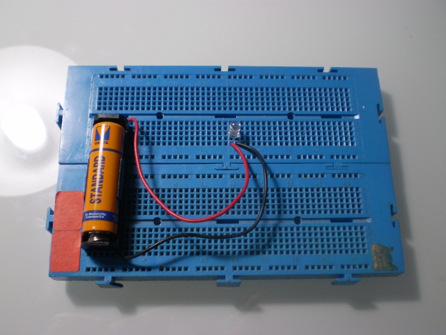 Bah! This standard 1.5V AA alkaline battery just doesn't have the flamin' minerals to power this 3V blue LED. Grr! Bah! This standard 1.5V AA alkaline battery just doesn't have the flamin' minerals to power this 3V blue LED. Grr!This came about after Nigel asked me to build a solar light, a project not yet started at the time of writing, and he showed me some schematics he’d pulled off the Interweb. Some were using inductors and I got to wondering why as none of the garden solar lights I’ve ever pulled apart have had ‘em. Turns out the inductor can be used with a resistor and transistor to construct a high frequency pulse generator which serves two purposes, ‘flashing’ the LED at a fast rate so it is not constantly illuminated making it more efficient when battery life drops low and ramping up the Voltage above that of the source supply to drive a higher Voltage load. 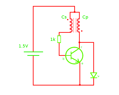 With the source Voltage below the load requirements, the circuit doesn’t require a dropper resistor to protect the LED making a further efficiency saving. The best part about this design is that is can be home made using scrap parts. A simple version can be constructed using some wire, a ferrite bead (or ‘torroid’), a 1k resistor and an NPN transistor. You’ll probably find a suitable bead (and possibly the transistor) readily available from scrap electronics such as a spent CFL bulb as I have. 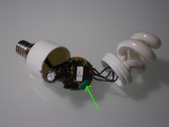 This deceased CFL has some recyclable components inside. At the end of it's life the bulb is designed to fail safely and may do so by popping certain components that form the ballast. It's wise to test any components retrieved from such a device. In my case, I'm going to remove the ferrite coil (arrowed) and nab a transistor. This deceased CFL has some recyclable components inside. At the end of it's life the bulb is designed to fail safely and may do so by popping certain components that form the ballast. It's wise to test any components retrieved from such a device. In my case, I'm going to remove the ferrite coil (arrowed) and nab a transistor.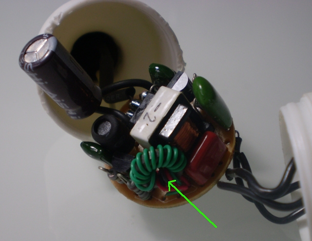 A close-up of that coil. Once cut from the PCB I'll be removing and discarding the existing wire as it's just the ferrite bead I'm interested in. 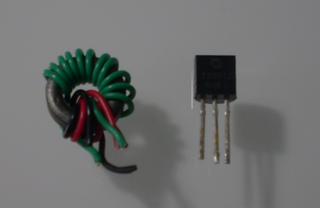 The coil and transistor removed. Many common NPN transistors can be used for this project although some are more suited than others. In my tests I've used a BC107, BFY51 and BC548 as they were to hand although 2N4401 and BC337 may be more suited to this role. It doesn't take much web-crawling to find recommendations. When it comes to making a Joule thief, the more times you can wind the wire wound around the ferrite bead the more efficient it will be. I'm using a very fine wire for my first attempt. Two coils are required so I've cut off a metre length and folded it in half. I can cut the folded end after winding to split the coils into two. 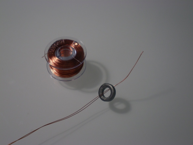 The folded end of the wire is thread through the centre of the bead (above) and wound around and around the bead as many times as possible (below). 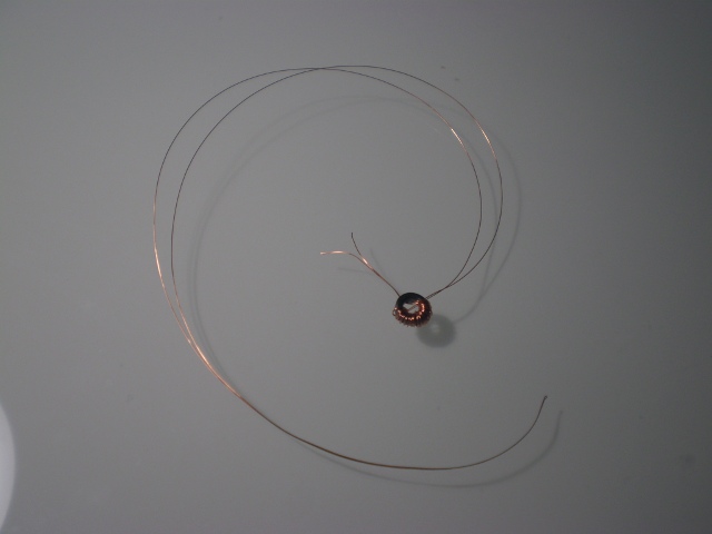 Finally the bead is fully wound. I've then cut the folded end leaving me with two separate coils however as shown in the schematic, the two coils have a common connection so it can be made a three legged component so long as the polarity of one coil is opposite the polarity of the other. 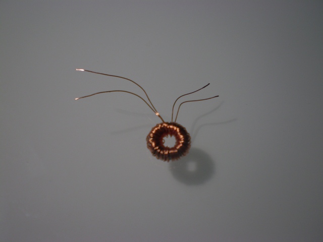 With the Joule thief built, the LED illuminates brilliantly from my single battery even though this particular battery is considered spent and has been pulled from the recycling box! 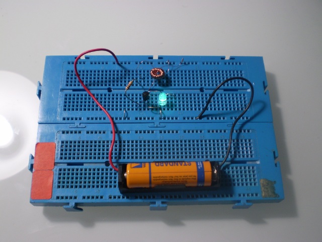 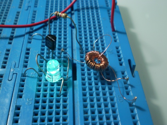 To explain how it works in a simplified way (which is all I understand about it), at power up current flows through the secondary coil and the resistor into the base of the transistor, switching it on. As the transistor becomes active, it opens the collector-emitter path allowing current to flow through the primary coil. As the LED requires 3V to light and the source is only 1.5V, the LED remains off and no current passes through it. The current through the primary coil into the collector is higher than that flowing through the secondary coil as it’s not limited by the resistor. This produces a positive feedback loop as the higher current through the primary coil creates a magnetic field that induces a Voltage in the secondary winding, increasing the input to the transistor base and making the transistor turn on harder. This opens the collector-emitter path further which increases current flow through the primary coil which increases induction in the secondary coil and so on. Almost immediately the transistor or the inductor core (or both) reach saturation. With the transistor saturated, there is no further gain and with the core saturated the magnetic flux cannot be increased. Either way, the rate of increase slows and this change in the rate causes a Voltage to be generated in the secondary coil opposing the source and decreasing the Voltage at the transistor base, quickly causing the transistor to reach it’s cutoff region. This effectively opens the collector-emitter path removing the current flow across the primary coil. The magnetic field of the primary coil collapses and as it does so it induces a Voltage that can be many times more than that of the source Voltage. This induced Voltage will need to dissipate through a load or it may damage the transistor by exceeding the transistor’s maximum collector Voltage rating. With a 3V LED connected, once the induced Voltage rises to the forward Voltage of the LED, the LED will conduct allowing the charge to pass through it, converting the energy into light as it does so. Once the magnetic field has completely collapsed and the induced Voltage has dissipated through the LED, we reach the start point again where the coils are de-energised and the transistor & LED are in a deactivated state. Once again, current then begins to flow through the secondary coil back into the base of the transistor and the cycle restarts. This oscillation flashes the LED but at such a high rate it cannot be seen due to the persistence effect of the human eye and so it appears constantly illuminated. These components allow a 3V LED to run off a single 1.5V battery because the circuit is ramping up the Voltage higher than the source to a point where it reaches the forward Voltage the LED requires. This increase in Voltage is at the expense of current so driving this circuit from a healthy 1.5V battery isn’t so efficient as it will consume more current than if the LED was driven directly from two 1.5V batteries in series. That said, for an application such as a garden solar light where the LED drains the battery overnight, the advantage of this circuit is that the LED will continue to illuminate brightly from it’s single battery even when the battery is heavily discharged. In fact, in my tests the LED will continue to put out light until the source drops below about 0.23V which is how the Joule Thief earns it’s name. The alternative of using two 1.5V batteries in series to drive a 3V LED directly may consume less current initially, but once the combined batteries are discharged below 2V the LED will extinguish as there isn't enough forward Voltage to drive it even though there is power still remaining in the batteries. Some sites suggest adding a 1nF capacitor from the bottom of the secondary coil to ground can improve transistor switching time further. The transistor itself dissipates very little energy, even at high oscillating frequencies, because it spends most of its time either in the fully-on or fully-off state so minimising the switching losses. Let's get this thing onto some test gear and take a closer look at what's happening.... 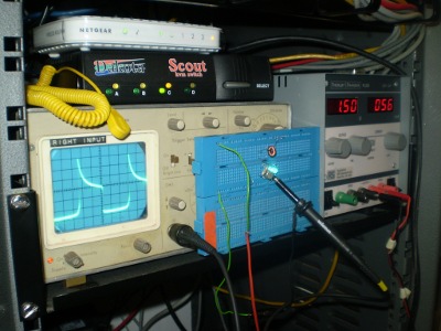 Running off a bench supply at 1.5V with these components shows a current of 56mA which is a lot more than the 20mA the LED would consume if connected directly to 3V DC (i.e. 2x 1.5V batteries). The waveform on the oscilloscope shows the Voltage surges to about 5V before the LED starts conducting and dragging it down. The waveform slopes as the LED conducts until the Voltage is spent and it quickly drops low again. The total time for each cycle is 25 microseconds so the transistor is switching at 40kHz (i.e. the LED is flashing 40,000 times a second. Notice also the mark/space ratio indicating the LED is on for approximately 2/5 of the cycle. 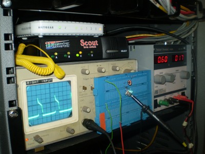 In this picture, the source has been dropped to 0.6V and the circuit is now consuming a more efficient 17mA. The surge Voltage appears to have dropped to around 3.5V and the cycle time is now 80 microseconds making a frequency of 12.5kHz. The LED is noticably dimmer but still operational. In this picture, the source has been dropped to 0.6V and the circuit is now consuming a more efficient 17mA. The surge Voltage appears to have dropped to around 3.5V and the cycle time is now 80 microseconds making a frequency of 12.5kHz. The LED is noticably dimmer but still operational.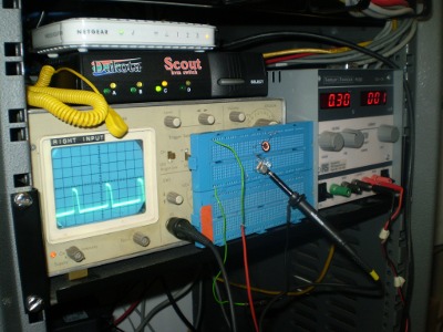 This time we're down to 0.3V and now only 1mA is being consumed. The LED is still on but is very dim by now. The surge Voltage is only 2.5V which is below what the LED is specified to run on so there is no longer a surge spike and the waveform is flatter across it's peak. Cycle time is 15 microseconds and frequency is 66.6kHz. Below 0.23V the LED fails to light and the waveform turns to noise. I made a second Joule thief using some cores from a scrap CAT-5 network cable which is much thicker. The ferrite bead is the same size so I get fewer turns because of the increased thickness of the wire's core and insulation. When first connected, it appears to work just as well as my first coil, but what's the real difference? Let's take a look... 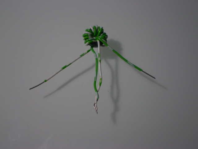 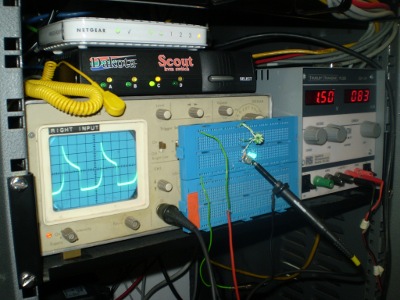 Works in just the same way on the face of it but take a closer glance and you'll see it's not so efficient. We're pulling 83mA at 1.5V now with a 9 microsecond cycle time giving a frequency of 111kHz. 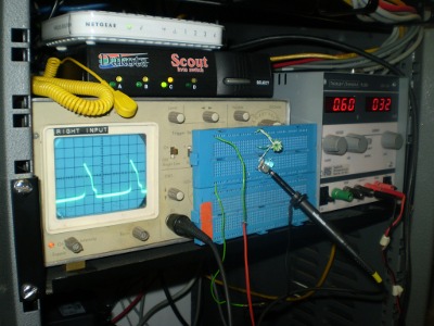 Drop the Voltage down to 0.6V and the current draw is still higher at 32mA. The surge Voltage is only hitting about 3V already. Time is 11 microseconds, frequency 90kHz. 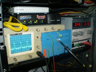 0.45V is the lowest I can go with this second coil as the LED extinguishes below this. 16mA is the current draw, 6.8 nanoseconds the time and 147kHz the frequency. 0.45V is the lowest I can go with this second coil as the LED extinguishes below this. 16mA is the current draw, 6.8 nanoseconds the time and 147kHz the frequency.So if you want to play with one of these, some fine gauge wire and plenty of windings are the key to making it more efficient. The real advantage to this thing is running a 3V LED from a source below 1V which is where the efficiency kicks in. For a homemade component requiring the addition of only a common transistor and resistor, this is a low cost way to maintain battery life for all sorts of projects where a LED needs to be illuminated for long periods or from small cells. I'm not sure it's suitable for the kind of requirement Nigel has in mind, but then that's another project. Update, 04/05/11 I'm indebted to Acme Fixer for the following comment:
Now this guy obviously knows his coconuts so I urge you to visit his site and read up. One thing I did tonight was to make a new JT using two metres of the fine wire and a BC337 transistor I managed to find amongst my junk. 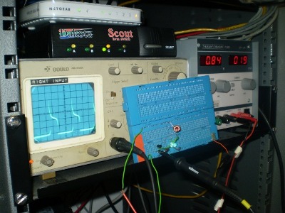 Above, using a BC337 transistor more suited to the role. At 0.84V the LED is still bright and the waveform healthy. Above, using a BC337 transistor more suited to the role. At 0.84V the LED is still bright and the waveform healthy.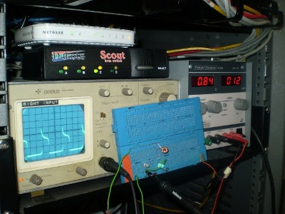 In this second picure, a BC107 transistor is being used. The waveform has dropped in Voltage and the frequency has increased. The LED is also noticeably dimmer. Just goes to show the right components really make a difference. In this second picure, a BC107 transistor is being used. The waveform has dropped in Voltage and the frequency has increased. The LED is also noticeably dimmer. Just goes to show the right components really make a difference.I also experimented with the suggestion to increase the resistance and two 1k resistors in series seemed to lower the current by quite a lot without a noticeable effect on the brightness of the LED. I obviously need to spend more time playing with this little fella to get my head around it so for those interested I recommend a trip to Watsons eBlog for further reading! |
No comments:
Post a Comment