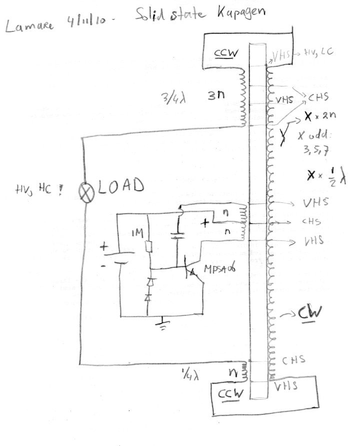
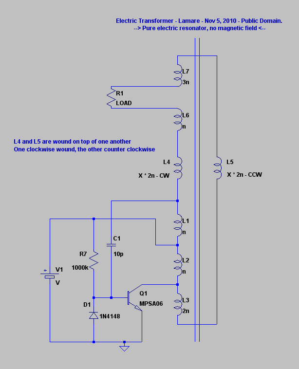
| The principle is that there is a certain parasite capacitance between coil windings, which stores a certain amount of energy. By winding the coil bifilar, you get substantial bigger voltage differences between adjacent windings and therefore more energy is being stored in these parasite/self capacitances. Since the energy stored in a capacitor equals 1/2 C V^2 ( Energy Stored on a Capacitor ), this is a significant difference in the amount of energy that is being stored in the coils self capacitance. And since in resonance, this energy is being flipped back and forth between the capacitance (voltage) and the inductance (current, magnetic component) you get significantly stronger oscillations in there. [...] What is interesting is to compare Tesla's bifilar wound coil from his patent with the top/bottom coils in the Kapagen device. As you can see, Tesla connected them in series, in order to get the voltage difference, while in the Kapagen device they are wound CW/CCW. So, with Tesla's coil, the voltage difference between adjacent windings is distributed across the coil, while with the Kapagen device, this increases from top (connected part) to bottom. Given that with the Kapagen device, we have different length short coils at the top and the bottom, this suggests that you probably may use this principle also at higher harmonics with the Kapagen way of winding and still get this voltage gain effect. You see, with Tesla's way of winding, you only get the situation that the magnetic field caused by the currents trough each half of the coil cancel each other out at the half wave resonance frequeny (over the whole coil), while with Kapagen's, they seem to always(?) cancel one another out, or at least at more than one higher harmonic. So, it seems that with Kapagen's way of winding, you can create a pure (longitudinal, "pressure-like") electric oscillation across the coil windings, without creating a magnetic field.... |
I also posted the idea for a solid state Kapagen device there:

Based on that, I came on this idea to use a dual layer coil, with one layer wound clockwise and the other counter clockwise, which would be L4/L5 in this schematic:
http://www.energeticforum.com/renewa...tml#post115219

Of course, these are not the same as the ringer circuit shown here, but maybe they are inspiring for further experiments....
Your almost there. Now try connecting your CW and CCW coils such that positive of one coil is connected to positive on the other coil. Neg to negative. If the two coils have the same number of turns simply leave one side say the negative side left unconnected to anything. Pass the other positive out through a diode to one plate of a DC capacitor and connect the other plate to Earth ground. If the coils have a different number of turns simply connect a load or high impedance between these wires that are positive to positive. They merely have different amplitudes. Say 100v and 220v for a gradient of 120v across the load. Works just fine.
ReplyDeleteYou can even have 6000v and 5880v giving 120v between to positives. Or same polarity sources. Whatever vokt level you desire by adjusting the difference in number of windings between the two coils. By doing this, you allow high energy density to be established but you determine what potential value you let it bleed out. If you build in resonance a strong energy and you limit or fix the voltage level it can only bleed out in higher amperage.
Delete